
Introduction
And another one in the box. Learned a lot of new concepts and it was also a great way to refresh my networking knowledge. This course is given by Keith Barker on CBT nuggets. The purpose of this document is to summarize some of the key learnings I got from the course.
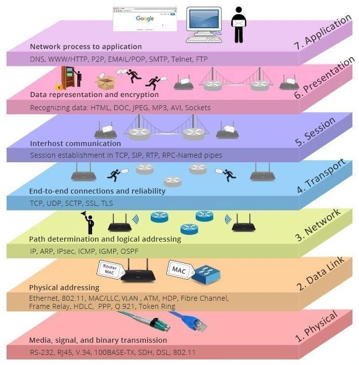
OSI Model
- Physical: copper, fibre, wifi, bluetooth, DSL, optical cable, coax cable
- Data Link: MAC address found with ARP
- Network: routing between networks, IP addresses
- Transport: Protocols include UDP, TCP, GRE
- Session: In the TCP/IP stack it is part of the Application layer 7
- Presentation: In the TCP/IP stack it is part of the Application layer 7
- Application
Network Topologies
- Bus: coax cable connecting computers at 10Mb/s. 1 Frequency and max 200 meters. 1 device can speak at a time by sending a broadcast
- Hub: Layer 1 device that repeats the frames. It has the same disadvantage as a Bus because there is 1 collision domain. Each computer can either send or receive. Max speed should be 0.5 duplex speed
- L2 Switch: smarter than a hub. One computer on the switch can communicate with another computer in the domain and there is no collision with other frames.
Network Types
- Peer to peer: emule, napster, uTorrent
- Client to server: web server
- Personal area network: NFC, bluetooth, infrared
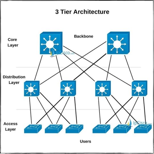
- Campus area network: 3 tier architecture
- Metropolitan area network
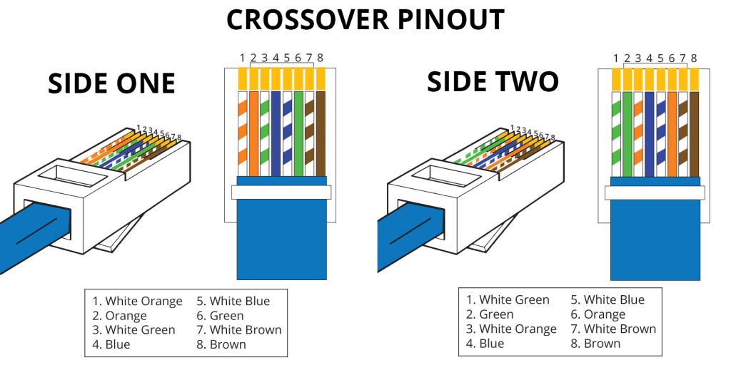
Cables and connectors
RJ45 has two standard: T568A(represented as A in the diagram below) and T568B(represented as B in the diagram below)
PC – L2 SW
A – A
PC – L2 SW
B – B
PC – PC (see diagram below)
A – B
When pin 1 on one side goes to pin 1 on the other side we call it a straight through cable. Otherwise it’s a cross over cable
Internet protocol
3 public ipv4 addresses defined in the RFC 1918
- 10.0.0.0 – 10.255.255.255 /8
- 172.16.0.0 – 172.31.255.255 /12
- 192.168.0.0 – 192.168.255.255 /16
private ipv4 addresses are either handed out by DHCP or they are configured manually on the machine. To make private ip addresses accessible over the internet you’ll either have to :
- Do port address translation
- Do network address translation NAT. You define a destination nat ip address and a service e.g. counter strike server
- Use a reverse proxy
Source NAT typically occurs when browsing the internet as a private ipv4 address makes its way to the internet. This generates a NAT table on the router so that it can properly route the response back to the user. Load balancers also do SNAT and swap internal addresses so that we make sure the replies go through him. The inital flow is the one that counts for us to distinguish SNAT and DNAT
Unicast
DNS is an example of unicast request. You receive an ip from your dns request and there is only one recipient for that DNS request
Multicast
is a method of communication where data is sent from one sender to multiple specific recipients simultaneously. Examples include streaming, online gaming and multi cast DNS. mDNS is useful to resolve IP address from hostnames when DNS is not working.
Broadcast
sent to everyone. ARP is an example. It is typically sent to the 255.255.255.255 address
Anycast
Multiple servers (usually in different geographic locations) are assigned the same IP address. e.g. google’s DNS 8.8.8.8
Subnet exercise 1
Give me the bit version of an ipv4 address 192.168.1.1
128 64 32 16 8 4 2 1
1 1 0 0 0 0 0 0 1 0 1 0 1 0 0 0 0 0 0 0 0 0 0 1 0 0 0 0 0 0 0 1
answer: 11000000 10101000 00000001 00000001
Subnet exercise 2
I want 4 new subnets from my 10.1.0.0/16, what are their network addresses?
2^1 = 2 not enough 2^2 = 4 not enough 2^3 = 6 is enough
16+3= /19
Number of host bits: 32 - 19 = 13 bits Number of possible IPs = 2¹³ = 8,192 addresses Usable hosts = 8,192 - 2 = 8,190 hosts
8 192 / 256 = 32 blocks
10.1.0.0/19 10.1.32.0/19 10.1.32.1 - 10.1.32.254 10.1.64.0/19 10.1.128.0/19
0+256 = 255 so why is the last address at 10.1.32.254? Because 255 is used for the broadcast address
Subnet exercise 3
I have 150 hosts, what subnet do I need?
2^8 = 256 256-2 = 254 32-8 = 23
192.168.0.0/23
Subnet exercise 4
How many hosts can I fit in a /27 network?
32-27 = 5 bits for the host 2^5 = 32 32-2 = 30 hosts -2 because we need one address for the broadcast and the other for the network
ipv6
addresses that start with 2 xxx or 3 xxx are global unicast addresses Link local addresses start with FE80 Multicast address groups start with FF There is no DHCP and no ARP just neighbor sollicitation and neighbor adverstisements
Application level services
SMTP over StartTLS 587
IMAP over StartTLS 143
SMTP over SSL(TLS) 465
IMAP over SSL(TLS) 993
DHCP: discover, offer, request, acknowledgment
the DHCP process goes through a three way handshake: syn, syn/ack, ack It is usually a local service but you can use a DHCP relay in case there is no DHCP server on the LAN
Network architectures
Access layer has L2 switches
IP routing
There are 3 ways routers learn about networks
- By being connected directly
- Static route: either default route or actual routing
- dynamic routing protocol: depending on your switch
- Distance vector method: RIP
- Link state: OSPF
- IGP: interior gateway protocol
- RIP
uses udp/520. I’m not sure how to configure this in the unifi envronment that we have but you basically advertise the networks that you can reach so that other routers know how to reach it as well.
routers send multicast to this address 224.0.0.9
- OSPF
uses its own protocol #89. routers send multicast to this address 224.0.0.5 or 224.0.0.6
Switching
If you’re building a closed system like the network used for a ceph cluster to sync its data in a proxmox cluster then using an L2 switch to connect all your computers together could be enough. But it is not enough to route traffic to other networks. You’ll need a router to hand out IP addresses and configure a gateway. In a 5 port L2 switch all of the broadcasts are sent to each physical interface. Each link is a full duplex connection which means we have 5 routes/collision domains.
ARP requests in this case are sent as a broadcast to everyone. PC1 for instance could advertise that it is looking for a mac address and a router that holds all of the mac addresses will then reply to that request.
Virtual Lans
VLANs are layer two broadcast domains that use an 802.1Q tag (header) to signify to your router that the layer 2 frame belongs to another network.
There are two primary ways to set up VLANs depending on whether the segmentation is handled at the switch level or the host (OS/network interface)
A. VLANs on Switches (Port-Based or Tagged VLANs)
-
Access Ports: Assigned to a single VLAN. The device connected to the port is unaware of the VLAN. All frames are untagged.
-
Trunk Ports: Carry traffic for multiple VLANs. Frames are tagged using 802.1Q so the receiving device knows the VLAN ID.
How it works:
-
VLANs are defined on the switch.
-
Ports are assigned to VLANs.
-
Trunk ports connect to other switches or routers, carrying traffic for multiple VLANs.
B. VLANs on Host Interfaces (Software/OS-Level VLAN Tagging)
Overview: The host machine (Linux, Windows, etc.) is configured to tag network traffic itself using virtual interfaces.
-
In Linux, this is often done using tools like ip, vconfig, nmcli, or /etc/network/interfaces.
-
Each VLAN gets a virtual interface (e.g., eth0.10 for VLAN 10).
How it works:
-
The host sends/receives tagged frames directly on a trunk port.
-
The switch port the host connects to must be a trunk port and allow the required VLANs.
Use case: Servers or VMs that need to be on multiple VLANs without needing separate physical NICs.
Spanning tree protocol
STP uses a bridge id to decide which routes have priority to block parallel paths and avoid broadcast storms/loops You’ll need to setup root guard/or bpdu filter to prevent hackers from claiming they have a new switch that has lower bridge port ids. There are other software security controls you can put in place to avoid users being able to trick an access port to become a trunk port or to block rogue DHCP servers.
QoS
Quality of service is a tag you set on a switch. Once the switch is under heavy load it will start to look at this tag to make forwarding decisions.
Redundancy
You can have a virtual ip address that acts as a load balancer for your gateway. Your windows client thinks he’s talking to one server but it’s actually a load balancer. This can be achieved with FHRP First Hop Redundancy Protocol or VRRP (virtual router protocol)
Security
skipped
Troubleshooting
when troubleshooting connectivity problems start by:
- Start by pinging the default gateway if that works, ping the address you’re trying to reach.
ping by default on linux uses udp but you can use a flag to use icmp packets instead.
- Is the network path going through a VPN tunnel? Or an SDN? In that case I would verify the MTU on those network adapters and make sure the values match along the tunnel.